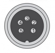
XLR-Wiring
From PROBOTIX :: wiki
Revision as of 16:55, 5 December 2018 by Admin (Talk | contribs) (Created page with "== XLR Pin-out/Wiring == {{XLR-Motors |1=Green (B-) |2=Black (B+) |3=NC |4=Red (A+) |5=Brown (A-) }} == Driver Dip-switches == {| class="wikitable" style="display: inline-blo...")
XLR Pin-out/Wiring

|
1) Green (B-) |
| 2) Black (B+) | |
| 3) NC | |
| 4) Red (A+) | |
| 5) Brown (A-) |
Driver Dip-switches
| Current Table ("ON=0", "OFF=1") | |||
|---|---|---|---|
| current | SW1 | SW2 | SW3 |
| 1.4A | 1 | 1 | 1 |
| 2.1A | 0 | 1 | 1 |
| 2.7A | 1 | 0 | 1 |
| 3.2A | 0 | 0 | 1 |
| 3.8A | 1 | 1 | 0 |
| 4.3A | 0 | 1 | 0 |
| 4.9A | 1 | 0 | 0 |
| 5.6A | 0 | 0 | 0 |
| Microstep Table | ||||
|---|---|---|---|---|
| Microstep | SW5 | SW6 | SW7 | SW8 |
| 2 | 1 | 0 | 0 | 0 |
| 4 | 0 | 1 | 0 | 0 |
| 8 | 1 | 1 | 0 | 0 |
| 16 | 0 | 0 | 1 | 0 |
| 32 | 1 | 0 | 1 | 0 |
| 64 | 0 | 1 | 1 | 0 |
| 128 | 1 | 1 | 1 | 0 |
| 5 | 0 | 0 | 0 | 1 |
| 10 | 1 | 0 | 0 | 1 |
| 20 | 0 | 1 | 0 | 1 |
| 25 | 1 | 1 | 0 | 1 |
| 40 | 0 | 0 | 1 | 1 |
| 50 | 1 | 0 | 1 | 1 |
| 100 | 0 | 1 | 1 | 1 |
| 125 | 1 | 1 | 1 | 1 |
SW4: "1"=Half Current; "0"=Full Current
