Difference between revisions of "PBX-MX"
From PROBOTIX :: wiki
m |
m |
||
| Line 17: | Line 17: | ||
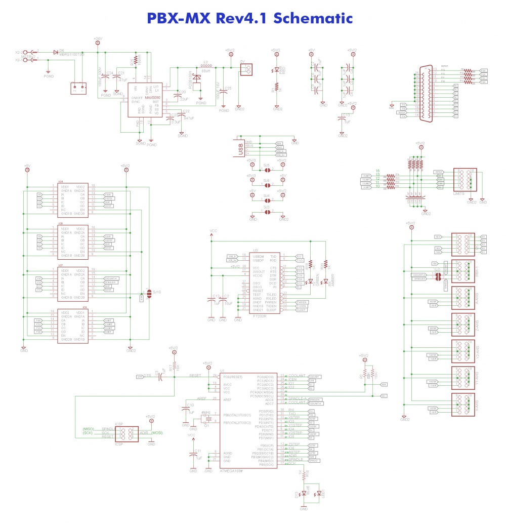
[[image:PBX-MX_rev4.1_schematic.jpg|1000px|PBX-MX Schematic]] | [[image:PBX-MX_rev4.1_schematic.jpg|1000px|PBX-MX Schematic]] | ||
| − | {| | + | {{ParallelPort |
| − | | | + | |1=A Dir |
| − | | | + | |2=X Step |
| − | | | + | |3=X Dir |
| − | | | + | |4=Y1 Step |
| − | | | + | |5=Y1 Dir |
| − | | | + | |6=Z Step |
| − | |11 | + | |7=Z Dir |
| − | + | |8=Y2 Step | |
| − | + | |9=Y2 Dir | |
| − | |12 | + | |10=X Limit |
| − | + | |11=Y1 Limit | |
| − | + | |12=Y2 Limit | |
| − | |13 | + | |13=Z Limit |
| − | + | |14=Spindle Relay | |
| − | + | |15=E-stop | |
| − | |14 | + | |16=Coolant |
| − | + | |17=A Step | |
| − | + | }} | |
| − | |15 | + | |
| − | + | ||
| − | + | ||
| − | |16 | + | |
| − | + | ||
| − | + | ||
| − | |17 | + | |
| − | + | ||
| − | + | ||
| − | + | ||
| − | + | ||
Revision as of 13:57, 14 June 2018
The PBX-MX can be used as an isolated parallel port breakout board for use with software such as LinuxCNC or Mach3. Includes an on-board Arduino compatible microcontroller that can be used for monitoring and diagnostics. There is a 10pin header for adding additional I/O through the Arduino.
The PBX-MX features an on-board switching power supply module that can accept up to 76VDC input and outputs a clean 2A@5VDC power rail.
The PBX-MX has 6 of our PBX-Headers for connecting to motor drivers, as well as an additional 10-pin header for limit/home/e-stop connections.
The PBX-MX also sports a 2-pin JST type connector for connecting a cooling fan. This connector outputs the same voltage as Vin.
We also moved the USB and DB-25 connectors out past the edges of the PCB so that you can now mount the breakout board to the rear panel of your enclosure.
D13 on the Arduino has an on board LED just like on all of the popular Arduinos and Arduino clones. We also placed an LED component near the USB connector where you can add an additional 3mm LED for back panel status reporting.


