Difference between revisions of "PBX-USB"
From PROBOTIX :: wiki
m (cleaned up formatting) |
|||
| Line 3: | Line 3: | ||
== Hardware Features: == | == Hardware Features: == | ||
| − | + | *4 axis USB CNC controller | |
| − | + | *USB (V2.x) from PC/Laptop running Windows XP, Vista or Windows 7(32 bit or 64 bit) | |
| − | + | *3 digital outputs (flood, mist, spindle) | |
| − | + | *25 KHz maximum step frequency | |
| − | + | *12us minimum pulse width | |
| − | + | *Buffered I/O for maximum performance | |
| − | + | *Two manual jog input keys per axis (8 total) | |
| − | + | *Two limit switches each for X,Y, Z (6 total) | |
| − | + | *Jog Pendant Interface ?Relay Board Interface | |
| − | + | *I2C Interface | |
| − | + | *E-Stop Loop | |
== Software Features: == | == Software Features: == | ||
| − | + | *Advanced interpolation algorithms | |
| − | + | *Control external devices with I2C protocol | |
| − | + | *Pause/resume of execution supported | |
| − | + | *Automatic homing procedure | |
| − | + | *Touch Plate Tool Change Procedure | |
| − | + | *Standard RS274/NGC G-code (EMC2 compatible) | |
| − | + | *Toolpath simulation | |
| − | + | *Advanced G-codes - G40, G41, G42 (Cutter Radius Compensation) supported | |
| − | + | *Advanced G-codes - G43, G49 (Tool Length Offsets) supported | |
| − | + | *Advanced G-codes - G54, G59.3 (Coordinate System Origins) | |
== Description: == | == Description: == | ||
| Line 32: | Line 32: | ||
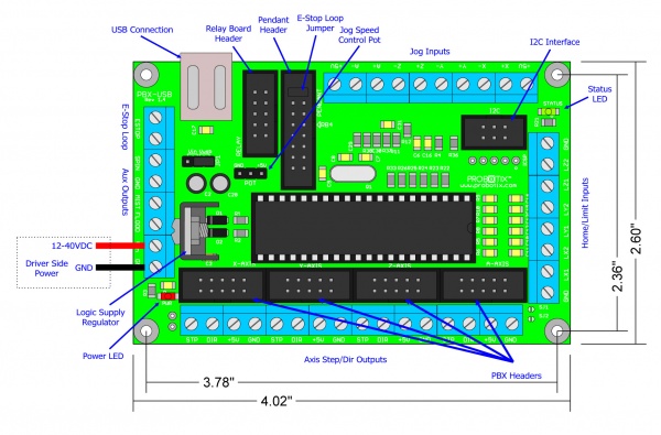
== Diagram: == | == Diagram: == | ||
| − | |||
| + | [[image:PBX-USB_diagram.jpg|600px]] | ||
[[image:PBX-Header.jpg|thumb|250px|Figure 1: PBX Header]] | [[image:PBX-Header.jpg|thumb|250px|Figure 1: PBX Header]] | ||
[[image:I2C-Header.jpg|thumb|250px|Figure 2: I2C Header]] | [[image:I2C-Header.jpg|thumb|250px|Figure 2: I2C Header]] | ||
| Line 63: | Line 63: | ||
|} | |} | ||
| − | + | == Notes: == | |
| − | + | * Step and Direction are printed reversed on the PCB | |
| − | Step and Direction are printed reversed on the PCB | + | |
| − | + | ||
Revision as of 18:40, 23 February 2018
Contents
[hide]Hardware Features:
- 4 axis USB CNC controller
- USB (V2.x) from PC/Laptop running Windows XP, Vista or Windows 7(32 bit or 64 bit)
- 3 digital outputs (flood, mist, spindle)
- 25 KHz maximum step frequency
- 12us minimum pulse width
- Buffered I/O for maximum performance
- Two manual jog input keys per axis (8 total)
- Two limit switches each for X,Y, Z (6 total)
- Jog Pendant Interface ?Relay Board Interface
- I2C Interface
- E-Stop Loop
Software Features:
- Advanced interpolation algorithms
- Control external devices with I2C protocol
- Pause/resume of execution supported
- Automatic homing procedure
- Touch Plate Tool Change Procedure
- Standard RS274/NGC G-code (EMC2 compatible)
- Toolpath simulation
- Advanced G-codes - G40, G41, G42 (Cutter Radius Compensation) supported
- Advanced G-codes - G43, G49 (Tool Length Offsets) supported
- Advanced G-codes - G54, G59.3 (Coordinate System Origins)
Description:
The PBX-USB is a USB interfaced CNC controller that was developed specifically to work with the CNC USB Motion Controller Software from www.planet-cnc.com. This Interface sports 4x 10 pin PBX-Header Connections for interfacing to our existing stepper motor drivers. It has an additional header for direct connection to our RBX-1 3 channel relay board. This software/hardware combination can be further expanded with jog key inputs and an I2C bus for nearly unlimited additional I/O. This will allow the development of jog pendants, digital readouts, and input/output cards for a variety of purposes. The software runs on Windows and replaces Mach3 or EMC2. It can even be run through a virtual machine on a Mac or Linux host.
Diagram:
Technical Details:
| JP1 | Vin - Powers micro-controller from 5V derived from Vin Vusb - Power micro-controller from USB (recommended) |
| POT | Connect a 10K logarithmic taper potentiometer to control jog speed. This signal is replicated in the pendant header (SPEED). |
| E-stop Loop | The E-stop loop is a normally closed circuit which loops through the 16-pin pendant header and the e-stop loop screw terminals. Any open condition in the loop will cause an e-stop. If e-stop switch(es) are not used, the circuit must be closed with jumpers. A small peice of wire will suffice to close the screw terminal loop. |
| Jog Inputs | The jog inputs can be used to make a simple jog pendant. Normally open push buttons connected to the jog inputs and the adjacent +5V connections will do the trick. |
| Limit/Home Inputs | Normally closed limit/home switch loops. You can use a single input for both + and - switches, or separate switch inputs for + & -. The LZ- input is used for the tool length compensation touch plate. |
| Aux Outputs | The spindle, mist, and flood outputs come out to the relay board header for direct connection to our RBX-1 relay board. Those signals are also replicated to the screw terminals for connection to other devices. The signal output cannot exceed 20mA or the micro-controller will be damaged. |
| I2C | Currently the I2C interface suports Spindle (M3, M4, M5), Coolant (M7, M8, M9), general purpose outputs (M62, M63, M64, M65), as well as current machine position. |
Notes:
- Step and Direction are printed reversed on the PCB


