Difference between revisions of "Unity Controller"
From PROBOTIX :: wiki
m (hide redundant image) |
(→Pin-Out) |
||
| (11 intermediate revisions by the same user not shown) | |||
| Line 1: | Line 1: | ||
| − | + | [[Category:CNC Controllers]] | |
| − | + | ||
| + | [[Image:Unity_Controller_rear1.jpg|thumb|500px|Unity Controller]] | ||
| − | + | Save time and money by having your stepper motor driver kit professionally wired and installed with the new Unity Controller - the only CNC control system you will ever need! | |
| + | * Expandable to your needs, versatile, and flexible. | ||
| + | * Can be used for 2, 3, 4, or 5 axis systems. | ||
| + | * Get it with or without motors | ||
| + | * Motors are pre-wired with 6 Feet of 5-Conductor 22Gauge Motor Wire and XLR connectors | ||
| − | + | == Have a look inside: == | |
| + | * 40Volt (110VAC Input) Linear Power Supply for the fastest motor operation | ||
| + | * Professionally wired, installed, mounted and tested electronics | ||
| + | * 5 Drivers, Breakout Board, IDC cables, and wired connector ports | ||
| + | * Full Enclosure with Power switch, fan, and fuses. | ||
| + | * Modular and organized | ||
| − | + | == Driver System: == | |
| + | The Unity CNC Controller includes 5 4.2amp MondoStep Bipolar Drivers, giving you versatility. Have a machine with two motors driving the gantry? No problem. You will still have a spare back-up driver for high-reliability, or use the spare for a rotary axis, and still be able to swap it over as a backup in case you have a driver failure in a high-reliability production environment. Mircostep settings are defaulted to 1/4 step (microstep setting of 4) but can be changed using the dip switches and corresponding key printed on the driver. | ||
| − | + | == Breakout Board: == | |
| + | The [[PBX-MX]] can be used as an isolated parallel port breakout board for use with software such as LinuxCNC or Mach3. Includes an on-board Arduino compatible microcontroller that can be used for monitoring and diagnostics. | ||
| − | + | == Integrated back panel includes: == | |
| − | + | * Connections for up to 5 motors | |
| − | + | * Connector for limit switches | |
| − | + | * Connector for E-Stop. | |
| − | + | * Earth ground connection for improved EMI protection | |
| − | + | * Auxilary 5v logic output that can drive an accessory like the powerswitch Tail II or other speed controller like the C6 spindle speed control board or SuperPID. | |
| − | + | * IEC power connections for the primary power and the router control relay. | |
| − | + | * Built in PWM to 0-10VDC analog signal interface for spindle speed control to a VFD or SuperPID. | |
| − | + | * PBX-MX Parallel Port Breakout Board | |
| − | + | * Two AC inputs | |
| − | + | * Color coded | |
| − | + | ||
| − | + | ||
| − | + | ||
| − | + | ||
<hr> | <hr> | ||
| − | |||
| − | |||
| − | |||
| − | |||
| − | |||
| − | |||
| − | |||
| − | |||
| − | |||
| − | |||
| − | |||
| − | |||
| − | |||
| − | |||
| − | |||
| − | |||
| − | |||
| − | |||
| − | |||
| − | |||
| − | |||
| − | |||
| − | |||
| − | |||
| − | |||
| − | |||
| − | |||
| − | |||
| − | |||
| − | |||
| − | + | [[Image:Unity_connections.jpg|1000px|Unity Controller]] | |
| − | + | <span style="background-color: orange; font-weight: bold;">A:</span> AC INPUT - Primary power input for power supply. | |
| − | + | ||
| − | + | ||
| − | + | ||
| − | + | ||
| − | + | ||
| − | + | ||
| − | < | + | <span style="background-color: orange; font-weight: bold;">B:</span> AC INPUT - Power input here is switched by relay to the (C) ROUTER output. |
| − | + | <span style="background-color: orange; font-weight: bold;">C:</span> ROUTER - Connect to the 110VAC 3-prong power cable from the machine harness. On-screen spindle controls, as well as M3/M5 g-codes will control this output. When a VFD spindle is used instead of a router, this outlet can be used with for a shop vac and is controlled by M8/M9. This relay is controlled by parallel port pin 14. | |
| − | + | ||
| − | + | ||
| − | + | ||
| − | + | ||
| − | + | ||
| − | + | ||
| − | + | ||
| − | + | ||
| − | < | + | <span style="background-color: DodgerBlue; font-weight: bold;">D:</span> USB - Connect to USB connector on PC. Powers the logic supply of the board. |
| − | + | <span style="background-color: DodgerBlue; font-weight: bold;">E:</span> PARALLEL PORT - Connect to the primary (built onto the motherboard) DB-25 connector on the PC. | |
| − | + | ||
| − | + | ||
| − | + | ||
| − | + | ||
| − | + | ||
| − | + | ||
| − | + | ||
| − | + | ||
| − | + | ||
| − | + | ||
| − | + | ||
| − | + | ||
| − | < | + | <span style="background-color: LimeGreen; font-weight: bold;">F, G, H, I:</span> MOTOR CONNECTIONS - Connect to each of the labeled motor connections from the machine harness. |
| − | + | <span style="background-color: LimeGreen; font-weight: bold;">J:</span> A-AXIS - For optional rotary axis. | |
| − | + | ||
| − | + | ||
| − | + | ||
| − | + | ||
| − | + | ||
| − | + | ||
| − | + | ||
| − | + | ||
| − | + | ||
| − | + | ||
| − | + | ||
| − | + | ||
| − | + | ||
| − | + | ||
| − | + | ||
| − | + | ||
| − | + | ||
| − | + | ||
| + | <span style="background-color: LimeGreen; font-weight: bold;">K:</span> VFD - Connect to 3pin VFD pigtail for speed control of a VFD spindle. | ||
| + | <span style="background-color: LimeGreen; font-weight: bold;">L:</span> LIMITS - Connect to the 8-pin limit switch connector from the machine harness. | ||
| − | + | <span style="background-color: LimeGreen; font-weight: bold;">M:</span> E-STOP - Connect to the 2-pin e-stop connector from the machine harness. | |
| − | + | ||
| − | + | ||
| − | + | ||
| − | + | ||
| − | + | ||
| − | + | ||
| − | + | ||
| − | + | ||
| − | + | ||
| − | + | ||
| − | + | ||
| − | + | ||
| − | + | ||
| − | + | <span style="background-color: red; font-weight: bold;">N:</span> EARTH GND - It is recommended that the machine is grounded to earth. Connect the two black wires from the machine harness to this connection. If using a VFD, ground the machine frame to the VFD earth ground terminal instead. Additional earth grounding may be necessary when working with certain spindles or certain types of materials that may cause excess EMI or static electricity. | |
| − | + | <span style="background-color: red; font-weight: bold;">O:</span> AUX -/+ - This is a 5V logic level signal that can be connected to a PowerSwitch Tail or other 5V@20mA relay circuit. This signal is controlled by the flood coolant controls in the software (M8/M9). The AUX output shares parallel port pin 16 with the VFD 0-10V signal, so it is only used if you are NOT using the VFD output. | |
| − | + | ||
| − | + | ||
| − | + | ||
| − | + | ||
| − | + | ||
| − | + | ||
| − | + | ||
| − | + | ||
| − | + | == Pin-Out == | |
| − | + | {{parport0 | |
| + | |1=A Dir | ||
| + | |2=X Step | ||
| + | |3=X Dir | ||
| + | |4=Y1 Step | ||
| + | |5=Y1 Dir | ||
| + | |6=Z Step | ||
| + | |7=Z Dir | ||
| + | |8=Y2 Step | ||
| + | |9=Y2 Dir | ||
| + | |10=X Limit | ||
| + | |11=Y1 Limit | ||
| + | |12=Y2 Limit | ||
| + | |13=Z Limit | ||
| + | |14=Spindle Relay | ||
| + | |15=E-stop | ||
| + | |16=PWMSpindle/AUX | ||
| + | |17=A Step | ||
| + | }} | ||
| − | + | {{XLR-EStop | |
| + | |1=Pin 15 | ||
| + | |2=GND | ||
| + | }} | ||
| − | 5 | + | {{XLR-Limits |
| + | |1=X Limit (Pin 10) | ||
| + | |2=GND | ||
| + | |3=Y1 Limit (Pin 11) | ||
| + | |4=GND | ||
| + | |5=Y2 Limit (Pin 12) | ||
| + | |6=GND | ||
| + | |7=Z Limit (Pin 13) | ||
| + | |8=GND | ||
| + | }} | ||
| − | + | {{XLR-VFD | |
| + | |1=24V in from VFD | ||
| + | |2=GND | ||
| + | |3=0-10V | ||
| + | }} | ||
| − | + | {{XLR-Motors | |
| + | |1=B- | ||
| + | |2=B+ | ||
| + | |3=NC | ||
| + | |4=A+ | ||
| + | |5=A- | ||
| + | }} | ||
Latest revision as of 11:51, 7 January 2022
Save time and money by having your stepper motor driver kit professionally wired and installed with the new Unity Controller - the only CNC control system you will ever need!
- Expandable to your needs, versatile, and flexible.
- Can be used for 2, 3, 4, or 5 axis systems.
- Get it with or without motors
- Motors are pre-wired with 6 Feet of 5-Conductor 22Gauge Motor Wire and XLR connectors
Contents
Have a look inside:
- 40Volt (110VAC Input) Linear Power Supply for the fastest motor operation
- Professionally wired, installed, mounted and tested electronics
- 5 Drivers, Breakout Board, IDC cables, and wired connector ports
- Full Enclosure with Power switch, fan, and fuses.
- Modular and organized
Driver System:
The Unity CNC Controller includes 5 4.2amp MondoStep Bipolar Drivers, giving you versatility. Have a machine with two motors driving the gantry? No problem. You will still have a spare back-up driver for high-reliability, or use the spare for a rotary axis, and still be able to swap it over as a backup in case you have a driver failure in a high-reliability production environment. Mircostep settings are defaulted to 1/4 step (microstep setting of 4) but can be changed using the dip switches and corresponding key printed on the driver.
Breakout Board:
The PBX-MX can be used as an isolated parallel port breakout board for use with software such as LinuxCNC or Mach3. Includes an on-board Arduino compatible microcontroller that can be used for monitoring and diagnostics.
Integrated back panel includes:
- Connections for up to 5 motors
- Connector for limit switches
- Connector for E-Stop.
- Earth ground connection for improved EMI protection
- Auxilary 5v logic output that can drive an accessory like the powerswitch Tail II or other speed controller like the C6 spindle speed control board or SuperPID.
- IEC power connections for the primary power and the router control relay.
- Built in PWM to 0-10VDC analog signal interface for spindle speed control to a VFD or SuperPID.
- PBX-MX Parallel Port Breakout Board
- Two AC inputs
- Color coded
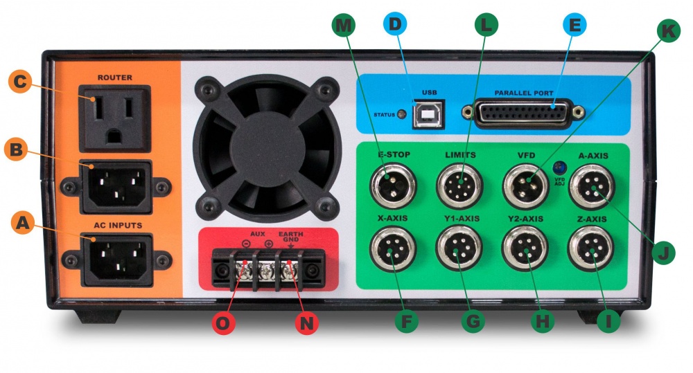
A: AC INPUT - Primary power input for power supply.
B: AC INPUT - Power input here is switched by relay to the (C) ROUTER output.
C: ROUTER - Connect to the 110VAC 3-prong power cable from the machine harness. On-screen spindle controls, as well as M3/M5 g-codes will control this output. When a VFD spindle is used instead of a router, this outlet can be used with for a shop vac and is controlled by M8/M9. This relay is controlled by parallel port pin 14.
D: USB - Connect to USB connector on PC. Powers the logic supply of the board.
E: PARALLEL PORT - Connect to the primary (built onto the motherboard) DB-25 connector on the PC.
F, G, H, I: MOTOR CONNECTIONS - Connect to each of the labeled motor connections from the machine harness.
J: A-AXIS - For optional rotary axis.
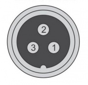
K: VFD - Connect to 3pin VFD pigtail for speed control of a VFD spindle.
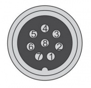
L: LIMITS - Connect to the 8-pin limit switch connector from the machine harness.
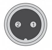
M: E-STOP - Connect to the 2-pin e-stop connector from the machine harness.
N: EARTH GND - It is recommended that the machine is grounded to earth. Connect the two black wires from the machine harness to this connection. If using a VFD, ground the machine frame to the VFD earth ground terminal instead. Additional earth grounding may be necessary when working with certain spindles or certain types of materials that may cause excess EMI or static electricity.
O: AUX -/+ - This is a 5V logic level signal that can be connected to a PowerSwitch Tail or other 5V@20mA relay circuit. This signal is controlled by the flood coolant controls in the software (M8/M9). The AUX output shares parallel port pin 16 with the VFD 0-10V signal, so it is only used if you are NOT using the VFD output.
Pin-Out
|
1) Pin 15 |
| 2) GND |
|
1) X Limit (Pin 10) |
| 2) GND | |
| 3) Y1 Limit (Pin 11) | |
| 4) GND | |
| 5) Y2 Limit (Pin 12) | |
| 6) GND | |
| 7) Z Limit (Pin 13) | |
| 8) GND |
|
1) 24V in from VFD |
| 2) GND | |
| 3) 0-10V |
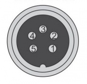
|
1) B- |
| 2) B+ | |
| 3) NC | |
| 4) A+ | |
| 5) A- |


