Difference between revisions of "RBX-1"
From PROBOTIX :: wiki
(Created page with "RBX-1 Relay Board") |
|||
| (2 intermediate revisions by the same user not shown) | |||
| Line 1: | Line 1: | ||
| + | [[category:Relay Boards]] | ||
[[image:RBX-1.jpg|thumb|500px|RBX-1 Relay Board]] | [[image:RBX-1.jpg|thumb|500px|RBX-1 Relay Board]] | ||
| + | The RBX-1 is a three-channel opto-isolated relay board which can be used to | ||
| + | switch high voltage devices such as spindle, coolant pumps, and vaccuums, from | ||
| + | your CNC control software and in your g-code files. Each relay is rated for 12 amps | ||
| + | at 120VAC (or 6 amps at 240VAC). There is an LED for each relay to indicate when | ||
| + | they are on. | ||
| + | The opto-isolators which drive the relays are common ground and fed with a | ||
| + | +5VDC signal from any un-used output pins from the breakout board. If your | ||
| + | parallel port does not output 5 volts or enough current to drive the LEDs inside of | ||
| + | the opto-couplers, a buffer chip needs to be used between the parallel port and the | ||
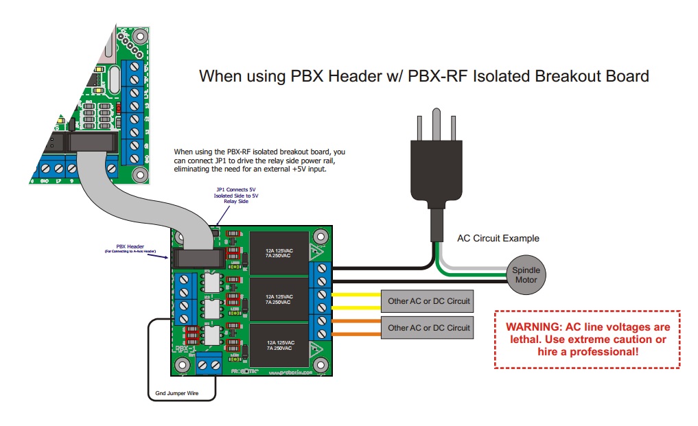
| + | opto-coupler. The best solution for this is the PBX-RF isolated breakout board, | ||
| + | which has the power to drive the opto-couplers. | ||
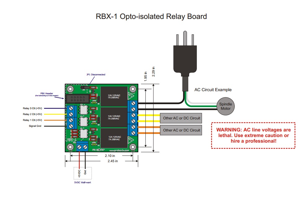
| + | The signals for the RBX-1 can be suppled through screw clamps on the RBX-1. | ||
| + | Also, there is an included PBX-header which makes connection to an empty drive | ||
| + | header on one of our breakout boards a snap. | ||
| + | The relay side of the opto-couplers require a 5VDC power supply. A 1 amp or | ||
| + | greater 5VDC wall-wart type power supply works well for this. When driven from the | ||
| + | PBX-RF isolated breakout board and using the PBX-header, JP1 can be installed | ||
| + | along with a ground jumper wire eliminating the need for the 5V power supply | ||
| + | [[image:RBX_wiring.jpg]] | ||
| + | [[image:RBX_PBXHeader.jpg]] | ||
Latest revision as of 18:01, 25 November 2013
The RBX-1 is a three-channel opto-isolated relay board which can be used to
switch high voltage devices such as spindle, coolant pumps, and vaccuums, from
your CNC control software and in your g-code files. Each relay is rated for 12 amps
at 120VAC (or 6 amps at 240VAC). There is an LED for each relay to indicate when
they are on.
The opto-isolators which drive the relays are common ground and fed with a
+5VDC signal from any un-used output pins from the breakout board. If your
parallel port does not output 5 volts or enough current to drive the LEDs inside of
the opto-couplers, a buffer chip needs to be used between the parallel port and the
opto-coupler. The best solution for this is the PBX-RF isolated breakout board,
which has the power to drive the opto-couplers.
The signals for the RBX-1 can be suppled through screw clamps on the RBX-1.
Also, there is an included PBX-header which makes connection to an empty drive
header on one of our breakout boards a snap.
The relay side of the opto-couplers require a 5VDC power supply. A 1 amp or
greater 5VDC wall-wart type power supply works well for this. When driven from the
PBX-RF isolated breakout board and using the PBX-header, JP1 can be installed
along with a ground jumper wire eliminating the need for the 5V power supply


