Difference between revisions of "Laser Module"
From PROBOTIX :: wiki
(Created page with "This is a placeholder for our installed Nebula option "Laser 2.8W 2.5amp Safety Compliant Laser Kit"") |
(→Retrofit) |
||
| (54 intermediate revisions by the same user not shown) | |||
| Line 1: | Line 1: | ||
| − | This is a | + | [[File:CNC_laser_1.jpg|right|300px|CNC LASER MODULE]] |
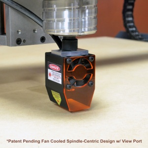
| + | Our Spindle Mounted Laser Module was developed in partnership with JTech photonics. You will find the official documentation on the laser itself here: | ||
| + | https://jtechphotonics.com/?page_id=602 | ||
| + | |||
| + | Starting with Software Configurator version 4.0, any file that ends in .ngcl extension will have all Z moves, tool references, and spindles controls removed when loading the file. These are then automatically replaced with the M-codes needed to control the laser. To use, simply create an engraving or profile tool path using any tool in the CAM software, either rename (or create a custom post processor to rename) the file to .ngcl extension. Load the file into LinuxCNC, drive the laser to about 1/8" about the part, and start the program. | ||
| + | |||
| + | You can also use the laser to set your part origin, buy using the "TEST LASER" button. When using this test mode, the laser is turned on at 10% power. This is still enough power to hurt you, but will allow you to see the beam without buring the material if only left on for a few seconds. | ||
| + | |||
| + | {{template:warning|1=Always wear laser safety glasses whenever in the same room with the laser and while drivers safety lockout key is inserted into the laser driver. Always remove the safety lockout key whenever the laser module is not in use.}} | ||
| + | |||
| + | == Setup == | ||
| + | |||
| + | Before using the laser, you need to adjust the focusing lens. | ||
| + | # Install the laser module module | ||
| + | # Lay a piece of scrap wood on the table | ||
| + | # Jog the machine to place the laser down to where it is approximately 1/8" above the surface of the scrap wood | ||
| + | # Put on your safety glasses | ||
| + | # Insert and turn on the safety lockout key | ||
| + | # Turn on the laser power switch | ||
| + | # Press the laser reset button | ||
| + | # Turn the mode switch into the ALWAYS ON position momentarily and observe the beam width, then turn it back to the left. | ||
| + | # Turn off the laser power switch and remove the safety lockout key | ||
| + | # Reach into the laser module and turn the focusing lens. You can slide the scra out of the way temporarily or you can remove the front shield from the module if you need. | ||
| + | # Repeat steps 5-10 until you have the smallest beam possible. | ||
| + | |||
| + | <br><br> | ||
| + | == Retrofit == | ||
| + | |||
| + | https://www.probotix.com/wiki/images/c/c5/Laser_wiring_diagram.pdf | ||
| + | |||
| + | Installation: | ||
| + | # Remove knockut from left side of outlet box, feed the wire through and glue the carriage connector plate to the side of the box with PVC cement. | ||
| + | # Mount the laser driver to the from of the machine on the left hand side. | ||
| + | # Feed the cable from the outlet box through the cable chain | ||
| + | # Connect the fan power to the JST connector and connect it to the fan connector on the laser driver. | ||
| + | # Connect the PWM control signals | ||
| + | # Install the laser e-stop contact into the e-stop enclosure and connect it to the laser driver. The e-stop switch has mounting points for two contacts. | ||
| + | # Connect the 12V power brick. | ||
| + | # Install the laser module into the spindle and connect it to the carriage connector plate. | ||
| + | # Run the appropriate software configurator to install the laser functionality. | ||
| + | #::[[PROBOTIX_Universal_LinuxCNC_Configurator]] | ||
| + | # Perform the laser focusing lens adjustment procedure. | ||
| + | |||
| + | |||
| + | [[File:Laser_retrofit_kit.jpg|500px]] | ||
| + | |||
| + | |||
| + | [[File:Old_interfaces.jpg|500px]] | ||
| + | |||
| + | |||
| + | [[Template:warning]] | ||
| + | |||
| + | ==Old info follows== | ||
| + | |||
| + | For safety reasons the laser will only turn on when running G-code. If for whatever reason the program is stopped (ie E-STOP is pressed) you must ensure to manually reset the laser driver board (red button) and turn off the power command via the sidebar LASER OFF button before running again. | ||
| + | |||
| + | {| align="center" style="border-spacing:0;width:5.5in;" | ||
| + | |- | ||
| + | | align=center style="border-top:0.05pt solid #000000;border-bottom:0.05pt solid #000000;border-left:0.05pt solid #000000;border-right:none;padding:0.0382in;" | Synchronized | ||
| + | | align=center style="border:0.05pt solid #000000;padding:0.0382in;" | M67 E0 Q# | ||
| + | |- | ||
| + | | align=center style="border-top:none;border-bottom:0.05pt solid #000000;border-left:0.05pt solid #000000;border-right:none;padding:0.0382in;" | Immediate | ||
| + | | align=center style="border-top:none;border-bottom:0.05pt solid #000000;border-left:0.05pt solid #000000;border-right:0.05pt solid #000000;padding:0.0382in;" | M68 E0 Q# | ||
| + | |- | ||
| + | |} | ||
| + | * E0 is the laser and is required to receive commands | ||
| + | * Q<nowiki>#</nowiki> is the power percentage to set (Q0 <nowiki>= OFF, </nowiki>Q100 = MAX power). | ||
| + | |||
| + | |||
| + | The <i>Synchronized</i> command will happen at the beginning of the next motion command. If there is no subsequent motion command, the command won’t happen. | ||
| + | * It’s best to always program a motion G code (G0, G1, etc) right after the M67. | ||
| + | * The “M67 E0 Q#” command is suggested as it prevents the laser from sitting in one spot longer than needed. | ||
| + | |||
| + | <pre> | ||
| + | M67 E0 Q100(turn on laser at 100% with next movement) | ||
| + | G01 X2 Y2 F40(laser turns on while moving into position) | ||
| + | ... do some other moves ... | ||
| + | M68 E0 Q0(turn off laser immediately) | ||
| + | G01 X3 Y3 F40 | ||
| + | </pre> | ||
| + | |||
| + | The <i>Immediate</i> command will perform the action immediately when the command is processed. | ||
| + | * The “M68 E0 Q0” command is recommended between tool paths to prevent drag lines. | ||
| + | |||
| + | <pre> | ||
| + | M68 E0 Q75(turn on laser at 75% now) | ||
| + | G01 X2 Y2 F30(move into position) | ||
| + | M68 E0 Q0(turn off laser now) | ||
| + | G00 X3 Y3(move to next position) | ||
| + | </pre> | ||
| + | |||
| + | Suggested combined usage: | ||
| + | |||
| + | <pre> | ||
| + | M67 E0 Q50(turn on laser at 50% with next movement) | ||
| + | G01 X2 Y2 F15(laser turns on while moving into position) | ||
| + | M68 E0 Q0(turn off laser now) | ||
| + | G00 X3 Y3(move to next position) | ||
| + | </pre> | ||
Latest revision as of 07:33, 24 October 2019
Our Spindle Mounted Laser Module was developed in partnership with JTech photonics. You will find the official documentation on the laser itself here: https://jtechphotonics.com/?page_id=602
Starting with Software Configurator version 4.0, any file that ends in .ngcl extension will have all Z moves, tool references, and spindles controls removed when loading the file. These are then automatically replaced with the M-codes needed to control the laser. To use, simply create an engraving or profile tool path using any tool in the CAM software, either rename (or create a custom post processor to rename) the file to .ngcl extension. Load the file into LinuxCNC, drive the laser to about 1/8" about the part, and start the program.
You can also use the laser to set your part origin, buy using the "TEST LASER" button. When using this test mode, the laser is turned on at 10% power. This is still enough power to hurt you, but will allow you to see the beam without buring the material if only left on for a few seconds.
| Always wear laser safety glasses whenever in the same room with the laser and while drivers safety lockout key is inserted into the laser driver. Always remove the safety lockout key whenever the laser module is not in use. |
Setup
Before using the laser, you need to adjust the focusing lens.
- Install the laser module module
- Lay a piece of scrap wood on the table
- Jog the machine to place the laser down to where it is approximately 1/8" above the surface of the scrap wood
- Put on your safety glasses
- Insert and turn on the safety lockout key
- Turn on the laser power switch
- Press the laser reset button
- Turn the mode switch into the ALWAYS ON position momentarily and observe the beam width, then turn it back to the left.
- Turn off the laser power switch and remove the safety lockout key
- Reach into the laser module and turn the focusing lens. You can slide the scra out of the way temporarily or you can remove the front shield from the module if you need.
- Repeat steps 5-10 until you have the smallest beam possible.
Retrofit
https://www.probotix.com/wiki/images/c/c5/Laser_wiring_diagram.pdf
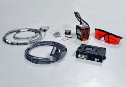
Installation:
- Remove knockut from left side of outlet box, feed the wire through and glue the carriage connector plate to the side of the box with PVC cement.
- Mount the laser driver to the from of the machine on the left hand side.
- Feed the cable from the outlet box through the cable chain
- Connect the fan power to the JST connector and connect it to the fan connector on the laser driver.
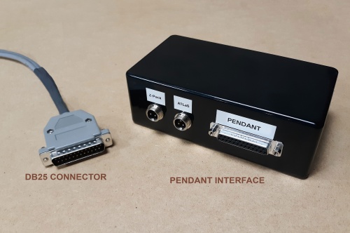
- Connect the PWM control signals
- Install the laser e-stop contact into the e-stop enclosure and connect it to the laser driver. The e-stop switch has mounting points for two contacts.
- Connect the 12V power brick.
- Install the laser module into the spindle and connect it to the carriage connector plate.
- Run the appropriate software configurator to install the laser functionality.
- Perform the laser focusing lens adjustment procedure.
Old info follows
For safety reasons the laser will only turn on when running G-code. If for whatever reason the program is stopped (ie E-STOP is pressed) you must ensure to manually reset the laser driver board (red button) and turn off the power command via the sidebar LASER OFF button before running again.
| Synchronized | M67 E0 Q# |
| Immediate | M68 E0 Q# |
- E0 is the laser and is required to receive commands
- Q# is the power percentage to set (Q0 = OFF, Q100 = MAX power).
The Synchronized command will happen at the beginning of the next motion command. If there is no subsequent motion command, the command won’t happen.
- It’s best to always program a motion G code (G0, G1, etc) right after the M67.
- The “M67 E0 Q#” command is suggested as it prevents the laser from sitting in one spot longer than needed.
M67 E0 Q100(turn on laser at 100% with next movement)
G01 X2 Y2 F40(laser turns on while moving into position)
... do some other moves ...
M68 E0 Q0(turn off laser immediately)
G01 X3 Y3 F40
The Immediate command will perform the action immediately when the command is processed.
- The “M68 E0 Q0” command is recommended between tool paths to prevent drag lines.
M68 E0 Q75(turn on laser at 75% now)
G01 X2 Y2 F30(move into position)
M68 E0 Q0(turn off laser now)
G00 X3 Y3(move to next position)
Suggested combined usage:
M67 E0 Q50(turn on laser at 50% with next movement)
G01 X2 Y2 F15(laser turns on while moving into position)
M68 E0 Q0(turn off laser now)
G00 X3 Y3(move to next position)


