Difference between revisions of "Unity Controller"
From PROBOTIX :: wiki
| Line 11: | Line 11: | ||
B: AC INPUT - Power input here is switched by relay to the (C) ROUTER output. | B: AC INPUT - Power input here is switched by relay to the (C) ROUTER output. | ||
| − | C: ROUTER - Connect to the | + | C: ROUTER - Connect to the 110VAC 3-prong power cable from the machine harness. On-screen spindle controls, as well as M3/M5 g-codes will control this output. When a VFD spindle is used instead of a router, this outlet can be used with for a shop vac and is controlled by M8/M9. |
D: USB - Connect to USB connector on PC. Powers the logic supply of the board. | D: USB - Connect to USB connector on PC. Powers the logic supply of the board. | ||
| Line 17: | Line 17: | ||
E: PARALLEL PORT - Connect to the primary (built onto the motherboard) DB-25 connector on the PC. | E: PARALLEL PORT - Connect to the primary (built onto the motherboard) DB-25 connector on the PC. | ||
| − | F, G, H, I: | + | F, G, H, I: MOTOR CONNECTIONS - Connect to each of the labeled motor connections from the machine harness. |
| − | J: A-AXIS | + | J: A-AXIS - For optional rotary axis. |
| − | K: | + | K: VFD - Connect to 3pin VFD pigtail for speed control of a VFD spindle. |
| − | L: | + | L: LIMITS - Connect to the 8-pin limit switch connector from the machine harness. |
| − | M: | + | M: E-STOP - Connect to the 2-pin e-stop connector from the machine harness. |
| − | N: EARTH GND - It is recommended that the machine is grounded to earth. Connect the two black wires from the machine harness to this connection. Additional earth grounding may be necessary when working with certain spindles or certain types of materials that may cause excess EMI or static electricity. | + | N: EARTH GND - It is recommended that the machine is grounded to earth. Connect the two black wires from the machine harness to this connection. If using a VFD, ground the machine frame to the VFD earth ground terminal instead. Additional earth grounding may be necessary when working with certain spindles or certain types of materials that may cause excess EMI or static electricity. |
| + | |||
| + | O: AUX -/+ - This is a 5V logic level signal that can be connected to a PowerSwitch Tail or other 5V@20mA relay circuit. This signal is controlled by the flood coolant controls in the software (M8/M9). | ||
Revision as of 06:41, 12 October 2015
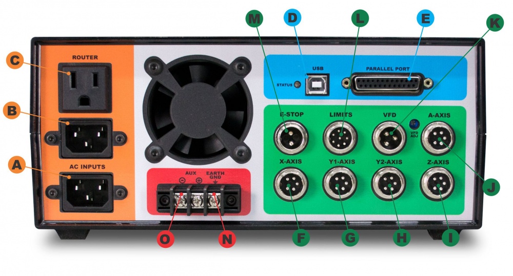
A: AC INPUT - Primary power input for power supply.
B: AC INPUT - Power input here is switched by relay to the (C) ROUTER output.
C: ROUTER - Connect to the 110VAC 3-prong power cable from the machine harness. On-screen spindle controls, as well as M3/M5 g-codes will control this output. When a VFD spindle is used instead of a router, this outlet can be used with for a shop vac and is controlled by M8/M9.
D: USB - Connect to USB connector on PC. Powers the logic supply of the board.
E: PARALLEL PORT - Connect to the primary (built onto the motherboard) DB-25 connector on the PC.
F, G, H, I: MOTOR CONNECTIONS - Connect to each of the labeled motor connections from the machine harness.
J: A-AXIS - For optional rotary axis.
K: VFD - Connect to 3pin VFD pigtail for speed control of a VFD spindle.
L: LIMITS - Connect to the 8-pin limit switch connector from the machine harness.
M: E-STOP - Connect to the 2-pin e-stop connector from the machine harness.
N: EARTH GND - It is recommended that the machine is grounded to earth. Connect the two black wires from the machine harness to this connection. If using a VFD, ground the machine frame to the VFD earth ground terminal instead. Additional earth grounding may be necessary when working with certain spindles or certain types of materials that may cause excess EMI or static electricity.
O: AUX -/+ - This is a 5V logic level signal that can be connected to a PowerSwitch Tail or other 5V@20mA relay circuit. This signal is controlled by the flood coolant controls in the software (M8/M9).


